Slip Ring Motor Connection Diagram Difference Between Slip R
[diagram] wiring diagram slip ring motor resistance starter Slip rings three motor rotor induction wound phase ring brush circuit concepts assembly rotating machine fig electrical engineering Slip ring motor rotor motors everything ever need know diagram ll resistance result added
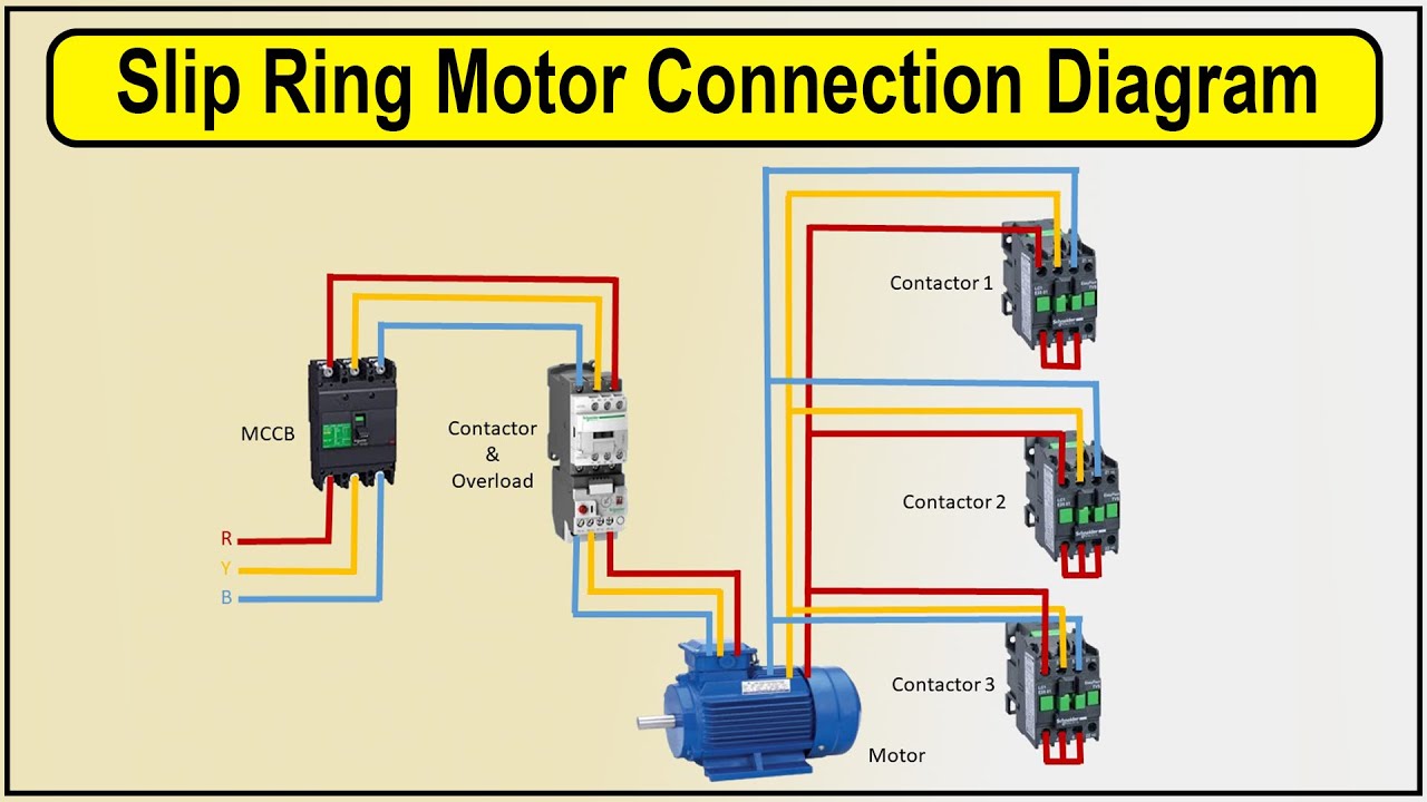
How to make Slip ring motor connection Diagram | 3 phase motor wiring
Self start 3-φ induction motor slip-ring wound rotor starter Schematic diagram of asynchronous slip ring motor What is slip ring induction motor? working principle, construction
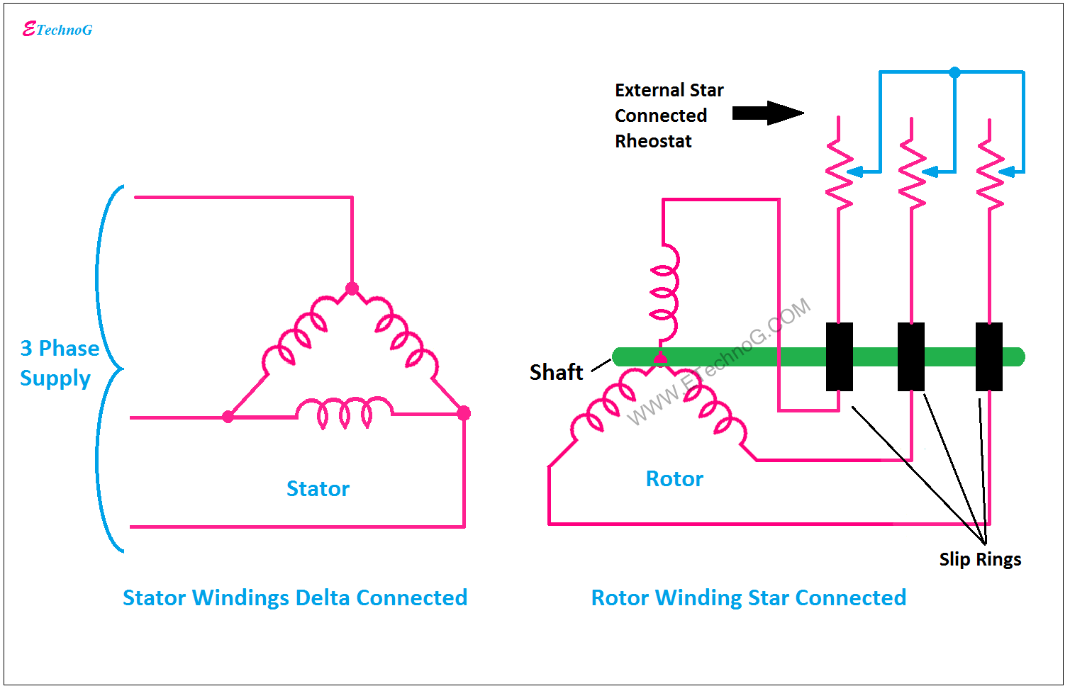
Slip motor induction ring star connected rotor delta diagram connection why simple very will always reasons explained problem which there
Slip ring induction motorSelf start 3-φ induction motor slip-ring wound rotor starter Slip induction disadvantages advantages55 slip ring motor starter wiring diagram wiring diagram plan.
Slip ring starter phase rotor power three diagram control diagrams electricaltechnology[diagram] wiring diagram slip ring motor Slip ring induction motor connection diagramEverything you’ll ever need to know about slip ring motors.

What is slip ring induction motor? working principle, construction
Slip ring induction motor, how it works?Slip ring motor connection diagram [diagram] wiring diagram slip ring motor resistance starterWhy the rotor of slip ring induction motor always star connected.
Understanding the basics of slip ring motor connectionSlip ring motor rings electrical torque ct scanner test monitoring works electric power diagram technology slipring wireless machine brush types How to make slip ring motor connection diagramSlip ring induction motor – learnchannel-tv.com.
Starting of an induction motor
12+ slip ring motor control diagramSelf start 3-φ induction motor slip-ring wound rotor starter Slip ring rotor or wound rotor in three phase induction motorThree phase slip ring rotor starter control & power diagrams / slip.
Slip ring vs. split ring: what are the key differences?How slip ring motor works for surveillance & video Electrical simplified: slip ringMotor slip induction ring cage between difference squirrel three circuit poles stator.

Self start slip ring induction motor starter power & control wiring
Slip ring induction motorOutstanding slip ring motor connection diagram 30 amp rv plug Slip ring induction motor control circuit diagramInduction elprocus torque.
Electrical schematic – motor starting system – slip ring motor startingSlip ring starter phase control rotor three diagram power diagrams motor wiring Slip ring induction motor, how it works?Electrical automation slipring rotor.

Motor induction starting circuit slip ring starter method methods connected supply phase diagram rotor circuitglobe connection start motors resistance rings
Difference between slip ring & squirrel cage induction motor withWhat is slip ring induction motor, working, advantages, disadvantages Motor slip ring induction explained phase gif tvMotor slip rotor wound ring induction rings diagram speed circuit electrical resistance secondary types.
What is slip ring induction motor? working principle, construction .


![[DIAGRAM] Wiring Diagram Slip Ring Motor Resistance Starter - MYDIAGRAM](https://i2.wp.com/www.electricaltechnology.org/wp-content/uploads/2020/05/Slip-ring-Induction-motor.png)